Solenoid Operated Directional Control Valve Symbol

Chapter 10 Directional Control Valves Part 4 Hydraulics Pneumatics

Valve Symbols Tameson
Pneumatic Circuit Symbols Explained Library Automationdirect

Hydraulic Symbology 201 Industrial Directional Valves
Iso Schemes Of Directional Control Valves
Solenoid Valve Symbols

G534 ng10 bottom.
Solenoid operated directional control valve symbol. Allow fluid flow and. They do not give any further information about the design flow orifice size etc. The vsd m and vpd m pilot operated directional control valves are available with either electric solenoid or hydraulic actuation of the main spool. Basics of the iso symbols.
Solenoid control valves that change position open close etc by opening small pilot circuits allowing pressurised air fluid or gas to move the valve are called pilot operated or servo pressure assisted valves. A water faucet is a good example of. 4 eaton vickers d03 ng6 and d05 ng10 solenoid operated directional valves explosion proof v vldi mc015 e january 2011 model code directional control valve dg4v 3s d03 ng6 dg4v4 01 d05 ng10 subplate mounted solenoid operated iso 4401size spool type 0 2 6 8. Subplate connection control method.
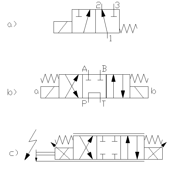
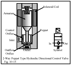
Each position the valve can take is represented by a square. 2 way d irectional control valves the 2 way directional valve often has 2 ports normally known as inlet and outlet. The top symbol shows a direct operated single stage directional valve with all ports blocked in the centre position. Schemes of directional valves the description of directional valves is standardized by din iso 121.
Solenoid control valves that change valve position open close etc by direct movment from a solenoid are called direct acting. Spool type application hydraulic machines connection type. Ft wdg series approximate weight size6 1 95kgs 4 29lbs. The following are different spool positions of schematic symbols that are commonly used in directional control valves.
Directional control valves perform only three functions. 6mm 10mm cetop3 cetop5 control method. These three functions usually operate in combination. Dg03 dg05 hydraulic directional valve valve size.
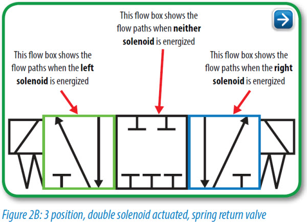
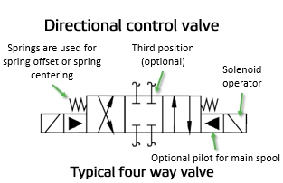
The only difference between this valve and symbol and those in figure 10 23 is that the pilot control is a double solenoid detented valve instead of. Configurable for internal or external pilot drains and options for pilot pressure reducing pilot chocks and main. However because this is a spool valve there will be some leakage between ports so the a and b lines may still be subject to experiencing different pressures and facilitating cylinder creep. When solenoid magnet a is energized the spool is pulled to left connecting the ports p to a and the ports b to tb when solenoid b is energized the spool is pulled to right connecting p to b and a to ta.
The simplest directional control valve is the 2 way valve. P is pressure inlet a and b are utilization ports ta and tb are return ports. Size10 5 90kgs 12 98lbs related parts. Change direction of fluid flow.
The valves are available in both 2 or 3 position and various spool flow patterns. The iso symbols display only the function of the valves.
Tip 18 Get Control Of Yourself Hydraulics Pneumatics

Directional Control Valves 5 2 Way Single Solenoid Valve Actuated By Solenoid And Pneumatic Piloting Air Spring Return Manual Override Valves Fluid Power Pneumatics Symbols Sluzby Odborne Vzdelavani A Vyukove Systemy Festo Didactic
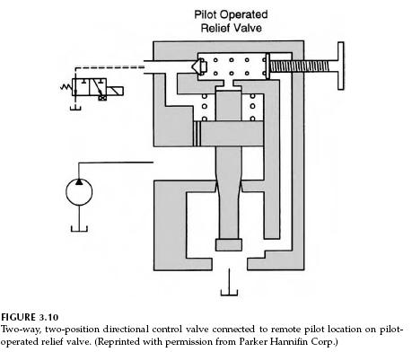
Pilot Operated Relief Valves Hydraulic Circuits Hydraulic Valve

Directional Control Valves Symbols Hydraulic Valve

Untangling Pneumatic Circuit Symbols Hydraulics Pneumatics

Solenoid Controlled Pilot Operated Directional Control Valve Youtube
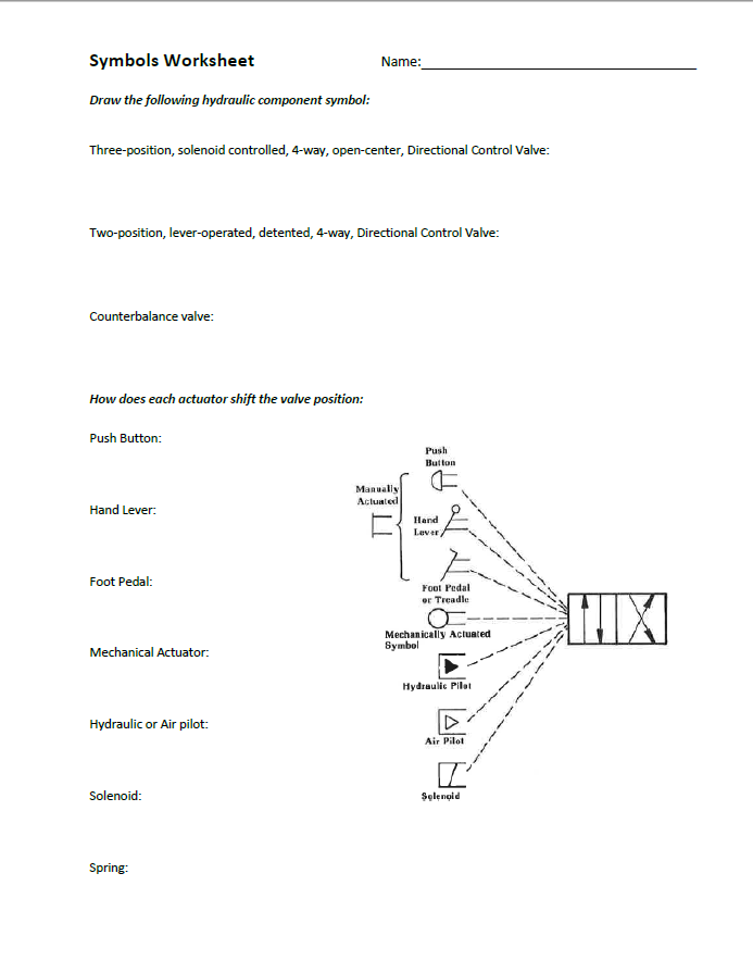
Solved Symbols Worksheet Name Draw The Following Hydraul Chegg Com
Reading Fluids Circuit Diagrams Hydraulic Pneumatic Symbols
Chapter 10 Directional Control Valves Part 3 Hydraulics Pneumatics

Nachi Sa Wet Type Solenoid Operated Directional Control Valve Zeus Hydratech

3 2 Way Pneumatic Valve How They Work Tameson

Hydraulic Pilot Operated Valves Hydraulic Valve
Directional Control Valve Directional Control Valve Mechanical Drawing Symbols Typical Hydraulic Cylinder Control Schematic

